Hacker Perspective: Telephony (basic information)
- Telephony (analog voice communication over wire) came in two fundamental categories: Circuit Switching and Packet Switching
- Circuit Switching includes everything from an operator patch panel (also called a plug board), to a step-by-step switch, to a crossbar switch, to SP1 (Canada) and 1ESS (USA) switches, to DMS switches.
- SP1 and 1ESS employed computers to set up analog connections via mini crossbar modules.
- DMS was digital in the switch, but was analog at its circuit end points.
- Packet Switching includes just about everything delivered by internet protocol. This began in earnest with computer applications like Skype but now also includes all so-called smart-phone communications which began with products like the BlackBerry
- This web-page is primarily dedicated to Circuit Switching
Telephone Information (part-1)
| Name | Description |
|---|---|
| CO |
|
| CDO |
|
| PBX |
|
| MDF |
|
| IDF |
|
Telephone Switchboard Plug
Many telephony signal names are derived from the operator's switchboard plug so let's start here
Telephone Information (Part-2)
| Name | Description |
|---|---|
| Tip |
|
| Ring |
|
| Sleeve |
|
| Wall Wires |
|
| Single Party Phone Wiring |
|
| Two Party Phone Wiring |
|
| On Hook |
|
| Off Hook |
|
| Pulse Signaling |
|
| Touch Tone Signaling |
|
| Ringing Signal |
|
| Sleeve Signaling |
|
| Busy Signal |
|
| All Trunks Busy Signal |
|
| Battery |
|
| Ground |
|
| ISDN |
|
| ADSL |
|
| VoIP |
|
Switching Information
| Name | Description |
|---|---|
| Operator Plug Board |
|
| Panel Board |
|
| Drop Relay |
|
| SxS |
Telephone companies knew about semiconductor technology because Bell Labs invented the bipolar junction transistor in 1948. So why did they stay with electromechanical technology so long? It was industry policy back then to squeeze every invested dollar out of the current technology until they were forced to move to the next. I met Gus Lorimer (a descendant of one of The Lorimer Brothers)
while working in the Preston C.O. in 1976. I reiterated my usual complaint about how Bell Canada would be better off ditching relays for transistors. He looked
at me glaringly then said "Anything you can do with transistors, I can do with relays" |
| 5xB |
|
| Computerized Circuit Switching, Analog Circuits |
|
| Computerized Circuit Switching, Digital Circuits |
|
| The migration to customer digital |
|
| ISDN |
|
| DSL |
|
| VoIP |
|
 Number 5 Cross
Bar (for local switching) Number 4 Cross Bar (for toll-tandem use)
Number 5 Cross
Bar (for local switching) Number 4 Cross Bar (for toll-tandem use) Carrier Information (only a few common technologies are listed)
| Name | Description |
|---|---|
| L1 N1 N2 |
|
| T1 |
|
| E1 |
|
| OC1 |
|
| ATM |
|
| LAN |
|
Step by Step (SxS) "Local Call" Overview
Telco wiring frames
- MDF ("main distribution frame" pronounced: "M. D. F.")
- primarily a two wire (tip + ring) frame allowing connections between the vertical side (VMDF), where the underground cable terminations appear, and the horizontal side (HMDF), where the OE (office equipment) terminations appear.
- the horizontal side of the MDF is permanently wired to the vertical side of the IDF using over head cabling.
- each line on the VMDF also contains electrical protectors known as "heat coils" and "carbons". The heat coils work like a very-slow-blow fuse protecting the
telephone switch from too much current while the carbons protected against lightning. Modern protectors employ gas cartridges in the place of carbons (unlike
carbons, gas cartridges can recover)
- IDF ("intermediate distribution frame" pronounced: "I. D. F")
- usually only associated with SxS
- primarily a three wire (tip, ring, sleeve) frame allowing connections between the vertical side (VIDF), where the OE (office equipment) blocks appear, and the horizontal side (HIDF) where the telephone number blocks appear.
- the vertical side of the IDF is permanently wired to line relays (OE) in the line finder bays
- the horizontal side of the IDF is permanently wired to telephone connector switch banks.
- Diagram: subscriber dials "3123" (short dialing demo; the first selector could absorb up to 3 digits if 7 were dialed)
- Every subscriber is connected to a dedicated pair of relays often just called "the OE" (the office equipment)
- line relay
- two windings of approximately 200 ohms each; one is connected to battery (-48 Volts) while the other is connected to ground (0 Volts)
- The line relay powers the telephone when it is off-hook.
- The circuit must not be too long (resistive) since the line relay must activate at a lower value of 14.8 mA.
- Ohm's Law tells us that a telephone line with a dead short inside the central office will not pass anymore than 120 mA (48/400)
- The DC resistance of a telephone is ~ 200 ohms (IIRC) so this sets a typical upper current limit of 80 mA (48/600). In practice you will never see current levels this high because the resistance of the copper wire between telephone and OE will reduce the current further.
- cutoff relay
- when active, this relay opens the line relay circuit blocking dial-tone activation
- line relay
- When the calling phone goes off hook, the completed circuit energizes the line relay which then requests the next-available line finder (there are usually only 20 line finders for every 200 lines which means that only 10% of the customers will be able to make a simultaneous out-going call)
- once a line finder connects to the line, the calling circuit is cut through to the first selector (line-finders are hardwired to first selectors). This causes a ground to be put back on the sleeve of the calling line which operates the cut-off (CO) relay, which causes the line relay to release (telephone phone power now comes from the A-relay of the first selector). The ground on the sleeve is also used to block incoming calls to the calling phone (green line on the diagram to the right). It is the first selector which provides dial-tone back to the subscriber as a signal to "begin dialing"
- the customer pulse-dials 3 pulses (at a speed of 10 pulses per second) the first digit which causes the 1st selector to step up 3 levels.
- The selector will then automatically step horizontally searching for an available path to the next selector bay (sleeve test: -48v=idle while 0v=busy)
- There are only ten circuits available on each horizontal so if the selector reaches step 11 (you have stepped too far) a small circuit is closed which will return the "all trunks busy" signal (120 IPM a.k.a. fast-busy)
- Assuming an idle circuit was found, the circuit is cut-through to the A-relay of the 2nd selector.
- the customer pulse-dials 1 pulse (at 10 pulses per second) which causes the 2nd selector to step up 1 level. The selector will then step horizontally looking for an available trunk to the connector bay (sleeve test: -48v=idle while 0v=busy)
- the connector dials 2 then 3 (the connector steps up '2' levels then steps horizontally '3' positions).
- the connector sleeve circuit is now used to operate the called subscriber's cut-off relay (thus disabling the associated Line Relay so the called customer can't draw dial tone when his phone goes off-hook)
- ringing signal (86 Volts AC) is now applied to the called subscriber's line
- when the call is answered, a DC path will interrupt the ringing signal and cut-though the voice path (tip and ring) over coupling capacitors
- The calling party's tip and ring will reverse polarity to indicate that the call was answered (this feature is used to collect coins or signal toll circuits to start timing the call)
Step by Step (SxS) "Local Call" Details
- SxS call detail: when a subscriber goes off hook...
- tip and ring line current causes a "line relay" (one associated with every subscriber's line) to operate which does two things:
- places battery (-48 volts via the C.O. relay) on the associated sleeve wire in the line finder top terminal bank
- operates a "group relay" to:
- ground the associated sleeve commutator in the line finder level switch bank (see picture below)
- starts the first available line finder stepping vertically
- a "line finder" switch starts to step vertically looking for the grounded commutator. Once it reaches the correct level, it rotates horizontally (stepping) looking for the subscriber line with battery on the sleeve (where it stops).
- now the subscriber's tip + ring circuits are cut-through to the A-relay of the "first choice" selector switch hardwired to the line finder. This first choice
selector switch also supplies the dial tone which is an audible indicator telling the customer to start dialing. Operation of the A-relay in the selector now causes
a ground to be placed upon the calling party's sleeve. This causes two things:
- operates the CO (cut-off) relay to release the line relay
- signifies that the calling line is busy at the calling line's connector bay.
- Most line finders were set up to service 200 lines but there were only 17-20 line finder switches which meant that only 10% of the customers in a line finder group could make outgoing calls at the same time.
- tip and ring line current causes a "line relay" (one associated with every subscriber's line) to operate which does two things:
- when the subscriber dials the first digit of the telephone number, the first choice selector will rise vertically an equivalent number of levels to the digit being dialed. The first choice selector will then step horizontally looking for an available trunk (it does this by testing the sleeve wiper looking for battery). If it steps to position eleven (a.k.a. "off the deep end") the subscriber will be presented with 120 IPM (a.k.a. all trunks busy tone)
- In a medium sized office (~40k lines) the first choice selector bay was usually wired to a fourth choice bay. This saved equipment and also allowed for something called short-dialing. Instead of dialing 7437970 you only needed to dial 37907. This means that if someone did dial all the digits, that a digit absorbing first selector was required to "eat the first two digits only if they were "74" (the switch would step up 7 levels and then just fall back the normal position; the same thing would happen if a 4 was dialed as the second digit). Short dialing was not usually available in densely populated areas.
- The fourth choice connector took care of the fourth digit of a 7 digit dialed number
- The fifth choice connector took care of the fifth digit of a 7 digit dialed number
- The connector took care of the last two digits (digit 6 was vertical stepping while digit 7 was horizontal stepping). At this time a DC connection exists between the A-relay of the connector and the calling party's telephone line. Ring signal (86 Volts AC) is now applied to the called party's line as well as an audible ringing tone onto the calling party's line as a form of feed back. When the called party is answered, a DC path exists between the connector and the called party's phone which trips the ring and cuts through the called party to the calling party by way of capacitors. At this same time the tip and ring of the calling party is reversed to signify that the call has been answered. This is used to do thing like "collect coins" from a payphone or "start a toll timer"
Example: Short-Dialing "7437970" (digits "74" are not required)
Historical overview from the 1940s:
- The following example comes from the Sherwood exchange in Kitchener Ontario Canada where the "SH" letters of Sherwood represent "74" on the telephone dial or
touch-tone keypad.
BTW, this name-number nomenclature was developed because it was thought that average people could not easily remember more than five numbers. There was nothing named Sherwood in the local community. This was just a mnemonic. - This was a 40,000 line step-by-step (SxS) exchange implemented as 742, 743, 744 and 745.
- The "74" prefix was redundant meaning that a local call could be completed by only dialing the last 5 digits
- If the local subscriber began dialing "74", the first selectors were wired in such a way as to absorb them (the switches stepped vertically but then fell back down)
- I suppose it goes without saying that whenever someone dialed "0" the circuit actually pulsed 10 times.
Historical overview from the 1960s:
- Then in the 1960s a 30,000 line cross-bar (5xB) was added to a floor above and implemented as 576, 578, and 579.
- The SxS office was modified so that SxS subscribers could directly connect to the 5xB exchange without needing to dial "1" (it was a local call, not long distance)
- A SxS subscriber wishing to call a 5xB subscriber would begin by dialing "5" (which was absorbed if it was the first digit) then "7" to make a connection to the crossbar exchange above. At this point, no one could use short dialing to call 745 numbers so short dialing was discouraged although it continued to work in a limited fashion.
Top Diagram (just below):
- Customer Goes off-hook to operate 1 of 200 line relays (two banks of 100; 10 up and 10 across)
- A line-finder steps up then across to "find the line relay" requesting dial tone (2 in this diagram)
- The back of each line-finder (Tip, Ring, and Sleeve) is hardwired to a first-choice selector which provides dial tone (signals "ready for you to continue")
- The customer dials the first digit (3 in this case) which caused the selector to step up 3 levels then automatically step across 1 to 10 terminals looking for an idle circuit (sleeve=-48v). It was designed to stop on the first idle circuit of ten.
       20 LF Switches |     | 20 First Choice Switches
 001 +                +-x≡x-+-> 0    Operator trunks (0)
 002 + <--------------+-x≡x-+-> 9    outbound trunks (911)
 003 +                +-x≡x-+-> 8    outbound trunks (893,894)
 ... +                +-x≡x-+-> 7    outbound trunks (576,578,579)
 ... +                +-x≡x-+-> 6    outbound trunks (632,648,669)
 ... +                +-x≡x-+-> 5 to fourth choice bay (745)
 ... +                +-x≡x-+-> 4 to fourth choice bay (744)
 198 +                +-x≡x-+-> 3 to fourth choice bay (743) ----+
 199 +                +-x≡x-+-> 2 to fourth choice bay (742)     |
 200 +                +-x≡x-+-> 1    Long Distance trunks (1+)   |
 ^^^----- 200 lines                                              |
+----------------------------------------------------------------+
| Fourth Choice Bay (743xxxx)        Fifth Choice Bay (7437xxx)
| (terminal bank view)               (terminal bank view)
|
Switch (dialed 7)                +-Switch (dialed 9)
+ 0-> to fifth choice bay (7430) | + 0-> to connector bay (74370)
+ 9-> to fifth choice bay (7439) | + 9-> to connector bay (74379)-+
+ 8-> to fifth choice bay (7438) | + 8-> to connector bay (74378) |
+ 7-> to fifth choice bay (7437)-+ + 7-> to connector bay (74377) |
+ 6-> to fifth choice bay (7436)   + 6-> to connector bay (74376) |
+ 5-> to fifth choice bay (7435)   + 5-> to connector bay (74375) |
+ 4-> to fifth choice bay (7434)   + 4-> to connector bay (74374) |
+ 3-> to fifth choice bay (7433)   + 3-> to connector bay (74373) |
+ 2-> to fifth choice bay (7432)   + 2-> to connector bay (74372) |
+ 1-> to fifth choice bay (7431)   + 1-> to connector bay (74371) |
+-----------------------------------------------------------------+
| 74379xx Connector Bay (terminal bank view; processes the
| final two dialed digits; here we go up 7 then across 10)
|
Switch (dialed 7 then 0)
+ 0 this vertical supports 7437901 up to 7437900
+ 9 this vertical supports 7437991 up to 7437990
+ 8 this vertical supports 7437981 up to 7437980
+ 7 this vertical supports 7437971 up to 7437970
+ 6 this vertical supports 7437961 up to 7437960
+ 5 this vertical supports 7437951 up to 7437950
+ 4 this vertical supports 7437941 up to 7437940
+ 3 this vertical supports 7437931 up to 7437930
+ 2 this vertical supports 7437921 up to 7437920
+ 1 this vertical supports 7437911 up to 7437910
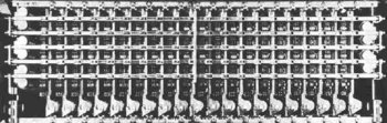
Small CDO (Community Dial Office)
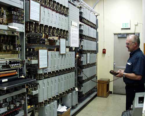
- The square area (middle top) contains 20 rows of rectangular relay covers. Each row contains:
- 10 line relays (one per subscriber)
- 10 cut-off relays (one per subscriber)
- 1 group relay
- This bay can support a maximum of 200 (20 x 10) subscribers.
- With 20 line finders for every 200 lines, only 10% of the subscribers will be to originate calls at the same time (sometimes more switches would be added to support businesses)
Connector Bay (2 rows of 11 switches; bottom middle-left)
- These switches processed the last 2 digits of the dialed number to connect to the dialed subscriber's line.
- The first connector was a special switch reserved for:
- allowing the operator to break into an "in-progress" call
- line testing by maintenance personnel
- Since each row has 11 switches, this picture most likely represents two separate connector shelves, each one supporting 100 terminating subscribers
Selector Bay (6 rows of 10 switches; far right)
- The six rows of switches on the far right appear to be a selector bay. Some of these will be wired to the connectors while others will connect to trunk circuits for carrying traffic to other telephone exchanges.
ROTS Bay (3 switches in extreme left)
- It is difficult for me to identify this equipment but it appears to be 3 ROTS (rotary outgoing trunk selector) switches just bellow the curved piece of paper. ROTS switches were sometimes used to access trunks (toll and non-toll) to remote locations.
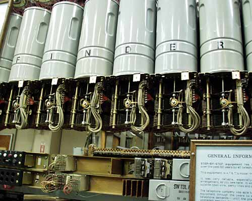
Line Finder Switches (a closer view)
- each switch contains 3 terminals banks x 10 levels x 10 rows x 2 connections for a total of 600 wires
- the lower bank contains tip + ring wires for customers 1-100
- the middle bank contains tip + ring wires for customers 101-200
- the upper bank contains sleeve wires for all 200 customers
- all 600 wires are daisy chained horizontally from bank to bank in the back of the bay (not visible here)
- the bank wiring between each switch is staggered in order to reduce the amount of "find" time for each OE. This means that "up one, in one" for switch 9 is terminal 91. However, terminal 91 is "up two, in one" on switch 8 and "up three in one" for switch 7.
- OEs 91-90 (and 191-190) will start switch 9 as their first choice line finder. If that switch is busy, the start lead is transferred to switch 8 and so on.
- the commutator (level seeking) wiper can be seen mounted to the middle of each shaft
- wiper wires have a cloth covering to allow increased flexibility
- two wire-spring relays can be seen below switches D & E (see the can covers). These are part of the bay alarm system.
- three wire-wrap blocks can be seen below switches I & N (see the can covers). These wires connect the bay alarm system to an aisle alarm.
- a black block below switch F contains indicator lamps and Alarm Cut Off (ACO) switches.
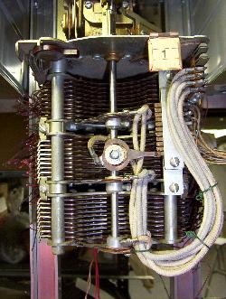
Line Finder Bank (up close)
- each switch contains 3 terminals banks x 10 levels x 10 rows x 2 connections for a total of 600 wires
- the lower bank contains tip + ring wires for customers 1-100
- the middle bank contains tip + ring wires for customers 101-200
- the upper bank contains sleeve circuits for all 200 customers (lower wiper: 1-100, upper wiper: 101-200)
- directly under the paper switch tag (with the number "1" on it) you'll notice eleven copper commutator contacts
- The bottom terminal was never used
- The top terminal was permanently grounded to prevent the switch from vertically over-stepping
- These contacts appear to be heavily oxidized which would never be allowed in a "production" telephone exchange (clean copper contacts are yellowish-orange rather than brown)
- the copper commutator wiper (mounted on the shaft) is currently making contact with the first (unused) commutator terminal. (this switch is sitting in the rest position; the tip, ring + sleeve wipers are not currently switched into the terminal bank)
- look carefully at the top bank wipers near the shaft and you'll see two wires indicating a path for both top and bottom circuits in that terminal bank. Barely visible in this picture are reddish-brown insulators between all three pairs of wipers as well as their respective contacts in the terminal bank
- wiper wires have a cloth covering to allow increased flexibility
- two green wire rings can be seen "dressing up" the wiper wires. These were necessary to prevent the wiper wires from flopping around which could result in them becoming snagged by the wipers.
- on either side of the terminal banks you'll notice a vertical brass tube (the right hand tube is partially blocked from view by the commutator terminal block). This tube contains an internal bolt which goes through a hole in the base plate of the switch and is then mated with a nut (not seen in this picture). Removing this nut allowed the switch to be removed from the bay and taken to a shop area for repair and/or adjustment.
SD Numbers
Documentation going back to 1928 states that the letters "SD" stand for "Schematic Drawing". However, you will hear telephone technicians also refer to "SD" as "Special Drawing" and "Switch Drawing". The following drawing numbers come from the May 1954 edition of "Training Manual for the Step by Step Dial Switching System" by American Telephone and Telegraph" (AT&T)
| SD Number | Function |
|---|---|
| SD-30200 | Selector |
| SD-30215 | Local Rotary Connector |
| SD-30220 | 2-Ring Combination Connector |
| SD-30228 | 1-Ring Combination Connector |
| SD-30537 | Incoming Pulse Correcting Repeater |
| SD-30976 | Digit Absorbing Selector |
| SD-32183 | Digit Absorbing Selector |
| SD-31114 | Toll Rotary Connector |
| SD-31179 | Toll Intermediate Selector |
| SD-31300 | Toll Connector - 10 Party Terminal per Station |
| SD-31401 | Test Distributor Control Circuit |
| SD-90018 | Test Trunk Circuit |
| SD-31501 | Interrupter Circuit & Transfer Key |
| SD-31647 | Reverting Call Selector |
| SD-31522 | Toll Transmission Selector |
| SD-31526 | Local Connector - 10 Party Terminal per Station |
| SD-31530 | Line Finder |
| SD-32133 | Subscriber's Line Circuit Line Finder Multiple Diagram |
| SD-31779 | Outgoing Repeater |
| SD-31592 | Coin Box Trunk |
| SD-32007 | Test Distributor |
| SD-61605 | Recording Completing Trunk-3 Wire |
| SD-32136 | Recording Completing Trunk-2 Wire Flat Rate |
| SD-62426 | Recording Completing Trunk-2 Wire |
| SD-31123 | Recording Completing Trunk-Coin Control (CDO) |
| SD-62428 | Recording Completing Trunk-Coin Control (Toll) |
| SD-62496 | Recording Completing Trunk-Coin Control |
Elisha Gray (true inventor of the telephone)
Publisher's Blurb (from the 2008 book: The Telephone Gambit):
While researching Alexander Graham Bell at MIT’s Dibner Institute, Seth Shulman scrutinized Bell’s journals and within them he found the smoking gun, a hint of deeply buried historical intrigue. Delving further, Shulman unearthed the surprising story behind the invention of the telephone: a tale of romance, corruption, and unchecked ambition. Bell furtively—and illegally—copied part of Elisha Gray’s invention in the race to secure what would become the most valuable U.S. patent ever issued. And afterward, as Bell’s device led to the world’s largest monopoly, the American Telephone and Telegraph Company, he hid his invention’s illicit beginnings. In The Telephone Gambit, Shulman challenges the reputation of an icon of invention, rocks the foundation of a corporate behemoth, and offers a probing meditation on how little we know about our own history.
This is a real pager-turner involving many people including Elisha Gray, Alexander Graham Bell and Thomas Edison to only name three of many. The author provides very convincing evidence that Elisha Gray should be credited for the invention of the telephone. Gray's confidential patent caveat, dated Feb-14, 1876, contains a drawing of a liquid-transmitter which is based upon a weak solution of sulfuric acid. Bell's patent, also dated Feb-14, contains no drawing of a microphone. Bell returns from Washington on Mar-8, 1876, then places a virtually identical drawing in his own notebook. Bell and Watson have the new idea working on March-10, 1876. Somehow (subterfuge?) Bell's patent application is updated after it is filed. There are allegations concerning the mental state of the main employee in the US patent office at that time being an alcoholic ex-civil-war soldier.
Accomplishments

- engineer, and a successful inventor (holder of ~ 70 patents)
- excerpt from the 2008 book: The Telephone Gambit: (P33): Then, in 1868, at the age of thirty-three, Gray received his first patent - for an improved telegraph relay. Initially, Gray conducted his electrical experiments in addition to farming. Building upon his patent's success, however, he soon helped start a firm called Barton & Gray to manufacture telegraphic equipment and he launched a full-time career as a manufacturer and inventor. Before long, Western Union, the vast U.S. company that held a near monopoly over the telegraph, recognized the impressive caliber of Gray's work. In 1872, the company bought one third interest in Gray's firm, making him a wealthy man. Gray's company changed its name to Western Electric, moved to Chicago, and soon became the lead developer and supplier of equipment to Western Union.
- Western Electric gets out of the wholesaling business in 1926 by selling off that division as Graybar
(an electrical equipment wholesaler still in business in 2026 in North America)
caveat: Western Electric continued to manufacture telephone hardware for the American telephone system. Northern Electric (later known as Nortel Networks) manufactured telephone hardware for the Canadian telephone system. Many (most?) of Northern Electric's products were based upon designs licensed from Western Electric. - possibly the first inventor of the telephone (if you do not count Philipp Reis)
- at the very least, a good case could be made for Gray and Bell being co-creators
- https://en.wikipedia.org/wiki/Elisha_Gray_and_Alexander_Bell_telephone_controversy
- Review of the 2008 book: The Telephone Gambit (anyone working in tech should read this book because it describes how a patented idea can be legally stolen)
- https://www.amazon.ca/Telephone-Gambit-Chasing-Alexander-Graham/dp/0393062066/
The Patent Controversy
Did Alexander Graham Bell plagiarize Gray's idea for the liquid-based telephone transmitter? It seems so. We know that an alcoholic patent clerk (Zenas Fisk Wilber) showed Bell a documents from Gray's confidential caveat (filing). But how could this have happened?
- everyone has heard the story of how "Bell submitted his patent four hours before Gray" but how many know that submitted patents were not time-stamped, and that anything submitted the same day was treated equally?
- on top of this, conflicting patents submitted on the same day always enter into something called an interference investigation but that did not
happen in this case
- or more accurately, an investigation was begun but was later withdrawn
- clerk Wilber sent interference letters to all concerned parties including Bell's attorneys: and Marcellus Bailey (a war buddy of WIlbur) and Anthony Pollok
- facts:
- on Feb-14, 1876 Bell filed a patent for the "harmonic telegraph" while Gray filed a caveat for the "telephone".
- what is a caveat? In those days it was treated as a 12-month place-holder indicating "more information will follow shortly" along with a "proof of invention" and the actual patent application
- since these were different inventions, could the clerk have been tricked into showing Alec Bell the caveat submitted by Gray?
- this is where we learn that someone inserted a lengthy hand-written entry into the margin of Bell's typed patent which appears to be a reworded description of "variable resistance" taken from Gray's caveat
- Bell races back to Boston then begins work on the telephone. He and Watson produce a working telephone on Mar-10, 1876
- On top of this, there is the troublesome line-drawing in Bell's notebook showing a man talking down into a cone. This same image can be seen in Gray's document which was filed on Feb-14, 1867 in Washington DC. Bell's notebook was never seen by anyone until 1976 (the 100-year anniversary of the telephone) when the Bell family donated a large trove of documents to the Library of Congress
- on Feb-14, 1876 Bell filed a patent for the "harmonic telegraph" while Gray filed a caveat for the "telephone".
- Elisha Gray was reputed to be a very honest man (in fact, he was a Quaker)
- Alec Bell was reputed to be a very honest man but he was also in love with the daughter of his investor and attorney, Gardiner
Green Hubbard. It appears that Hubbard may have engineered the conflict between Bell and Gray by using Bell's emotions for Hubbard's daughter as leverage (we all
know how that usually turns out)
- Bell's behavior in the year after the patent does not seem to be the behavior of an inventor. In fact, it seems the behavior of someone with a guilty conscience
Links
- https://en.wikipedia.org/wiki/Elisha_Gray_and_Alexander_Bell_telephone_controversy
- Review of the 2008 book: The Telephone Gambit (anyone working in tech should read this book because it describes how a patented idea can be legally stolen)
- https://www.amazon.ca/Telephone-Gambit-Chasing-Alexander-Graham/dp/0393062066/
Thomas A Watson
The Thomas A. Watson version of the story I am familiar with is somewhat more complicated than the versions published by newspapers, magazines and movies.- The Charles Williams Machine Shop (of Boston) was a manufacturer of fine electrical instruments -and- had a side line doing consultant engineering.
- Back in those days, no one could afford a full time engineer so they would take their ideas to a consulting engineer, or a company that hosted
consulting engineers.
observation: During this same time period, Arthur Conan Doyle was a consulting physician (ophthalmologist) who would not get a patient referral for weeks. To keep himself busy, he wrote fictional stories about a consulting detective by the name of Sherlock Holmes
- Alexander Graham Bell took his ideas for the telephone to the Charles Williams Company where he was assigned to a consulting engineer by the name of Thomas Watson.
- At the urging of Bell's future father-in-law, Gardiner Greene Hubbard, Watson is convinced to
leave Charles Williams and work full time with Bell. Apparently, Hubbard paid to equip the new lab and bank-rolled Watson's fee.
- full time research? sounds to me like the precursor to Bell Labs
- Thomas A. Watson's only son, Thomas J Watson, becomes a rising star at Computing-Tabulating-Recording Company which he later morphs into IBM
- Many people today are surprised to learn that Thomas Edison also employed the Charles Williams Machine Shop before he built his own research facility in Orange, New Jersey. In fact, Edison maintained an office in the same building just so he could get quick access to the human talent.
A few related links:
- http://www.telegraph-office.com/pages/Charles_Williams.html
- http://www.telegraph-history.org/charles-williams-jr/index.html
Examples of synchronicity (and cross-fertilization)
- Bell Labs invents the transistor which revolutionizes IBM's computer business (see: IBM 7070) as well as the telephone system hardware (see: 1ESS)
- Bell Labs invents the Unix operating system then creates the C programming language in order to produce a better version of Unix. This action is so successful that the C language takes off on its own as an alternative to assembly language making it the first truly portable computer language.
- Since Bell Labs is run as a monopoly, they are not allowed to profit from Unix so many universities get it for free, or at a very low price license (under one thousand dollars). They use access to the source code to teach computer engineering and one variation at the University of California at Berkley becomes very popular and is called BSD Unix.
- Since universities are not chartered to sell software, BSD Unix is given away when possible or licensed at cost (once again, under one thousand dollars)
- DARPA had been working with Universities to develop software for something that would eventually be called the Internet. They focus on a talented C-language programmer at Berkley named Bill Joy to write the TCP (transmission control protocol) code which would be built on top of IP (internet protocol) which would eventually be known as TCP/IP. Not only does this enable the US government to build a command-and-control system able to survive a nuclear attack, it provides the computer industry with the internet. It also enables the telephone industry to move from "circuit switching" to "packet switching" which later is used for VOIP (voice over IP). It should be no surprise that a faster internet is able to support Video over IP. From this point on, TCP/IP is given away for free as part of Unix.
- the C programming language morphs into the object-oriented C++ programming language
- The breakup of the Bell system under Ronald Regan causes UNIX to come under control of AT&T. Universities are told they will no longer get UNIX or UNIX source
code (which they need to teach computer engineering) at bargain-basement prices.
- This causes them to focus their collective efforts on alternatives to AT&T Unix like "BSD Unix", GNU, and MINIX.
- GNU is basically a total rewrite of AT&T Unix apps to avoid copyright claims. The GNU project did not have the skills to produce an alternate kernel.
- Enter Linus Torvalds with an alternate kernel but no apps. Put them together and you end up with Linux (the most popular operating system in the world which changes the computer industry forever; even IBM joins in with )
- Events like these kick off the open source movement
- Smart phones from companies like Blackberry, Apple (iPhone) and Google (Android) allow the telephone to morph into a handheld computer
Links
- http://connectionsmuseum.org
- Welcome to Bell Canada's technological archives
https://www.youtube.com/watch?v=OnNfwuN9Hgg - AT&T Tech Channel :: https://www.youtube.com/@ATTTechChannel
- AT&T Archives: The Step-By-Step Switch :: https://www.youtube.com/watch?v=xZePwin92cI
- The Transistor :: https://www.youtube.com/watch?v=V9xUQWo4vN0
- The Crossbar Switch :: https://www.youtube.com/watch?v=myqHoVcHkkA
- BELL HOMESTEAD ~ National Historic Site ~ 94 Tutela Heights Rd. Brantford, Ontario, Canada.
- http://www.telephonetribute.com/
- Almon Strowger @ Wikipedia
- Telephone exchange @ Wikipedia
- How The World Was One is a non-fiction book about telecommunications by Arthur C. Clarke
- https://atlantic-cable.com/
- Bell System Memorial (1876-1983) http://www.BellSystemMemorial.org
- Considering the poor state of telephone communications today, I think it is safe to assume that breaking up "The Bell System" (the way it was done) was a huge mistake. Although transitioning from circuit switching to packet switching was obvious and necessary, Bell System engineers would have made sure everything worked properly before rolling it out to their subscribers. How is it that we still experience "dropped calls" and "ring without call completion" in 2009? ("can you hear me"?)
- The Bell System supported Bell Labs whose scientists and technicians invented stuff like the Transistor (in various forms), MASER, and LASER. They also gave the world the UNIX operating system as well as the C and C++ programming languages. Who is going to do pure research today?
 Back to Home